
From jumper wires to a custom PCB: building the HC-01 humidor controller
Jerome Privott · · 4 min read
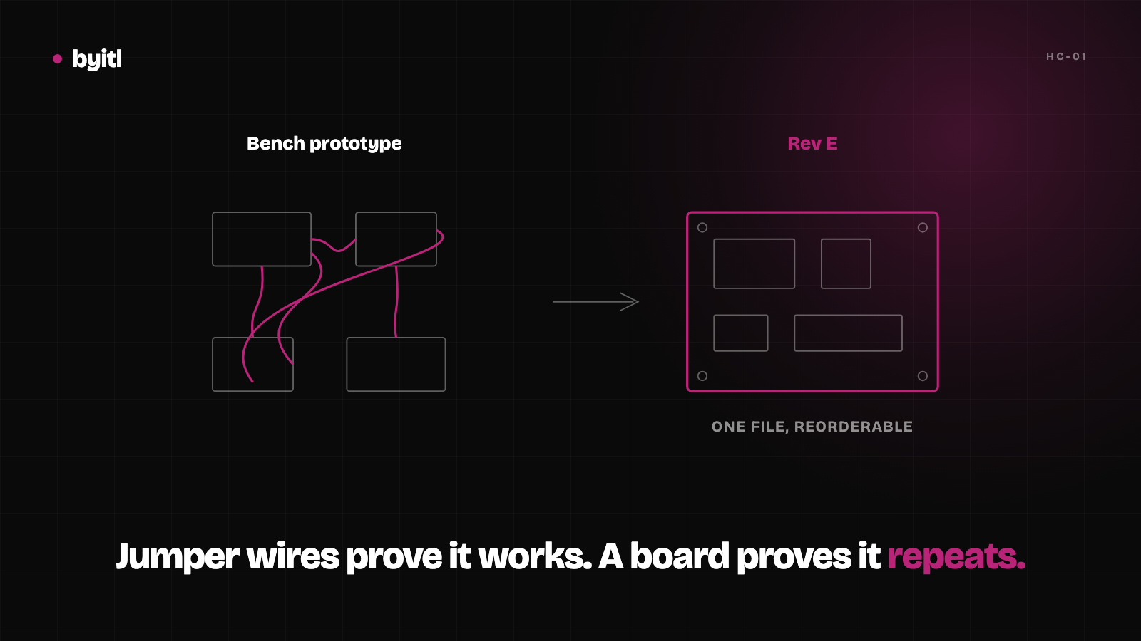
Most hardware projects start the same way: somebody has a board that works on their bench, and they need it to become a product. We built the HC-01 humidor controller partly because we wanted one, and partly because doing the whole thing ourselves — board, firmware, enclosure — is the fastest way to find out where that handoff actually breaks.
It breaks in more places than you'd think. Here's the honest version.
The prototype was a mess, and that was fine
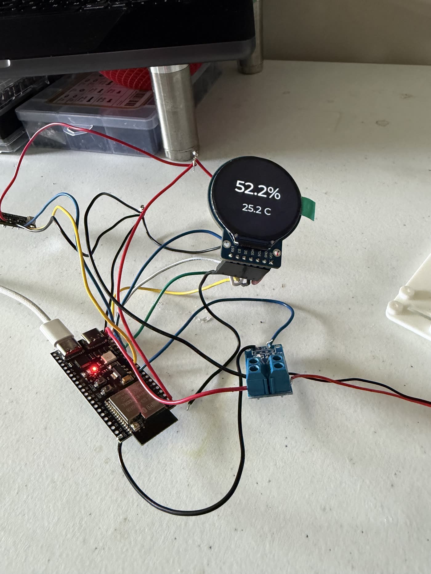
That's the first real milestone: an ESP32 dev board, a 1.28-inch round TFT, an SHT40 temperature/humidity sensor, and a MOSFET module to switch the fan — reading 52.2% RH and 25.2 °C off the bench.
Nothing about it is precious. It's a dev board, jumper wires, and a sensor breakout, and it exists to answer one question: does the idea work at all? Once it did, every remaining problem was a packaging problem.
That's the moment most people come looking for help. The circuit is proven and the product doesn't exist yet.
The mistake: we never measured the sensor
Here's the one that cost us a reprint.
The SHT40 is a tiny part. The breakout board it ships on is not. Our design agent sized a mounting pocket around what the sensor looked like it should be — roughly 12 × 10 mm — and printed it. The actual breakout is about 25 × 18 mm with four mounting holes. Not close. The part didn't sit in the pocket, and the pocket wasn't the sort of thing you open up with a knife.
The lesson isn't "measure twice." It's more specific than that: the thing you're designing around is the breakout, the connector, and the wire bend radius — not the chip in the datasheet. A 3 × 3 mm sensor with a 25 mm carrier board is a 25 mm part. We now refuse to model a component we don't have exact geometry for, from a STEP file, a datasheet drawing, or calipers on the real thing. Guessing feels faster right up until the print finishes.
The display told us where the lid had to be
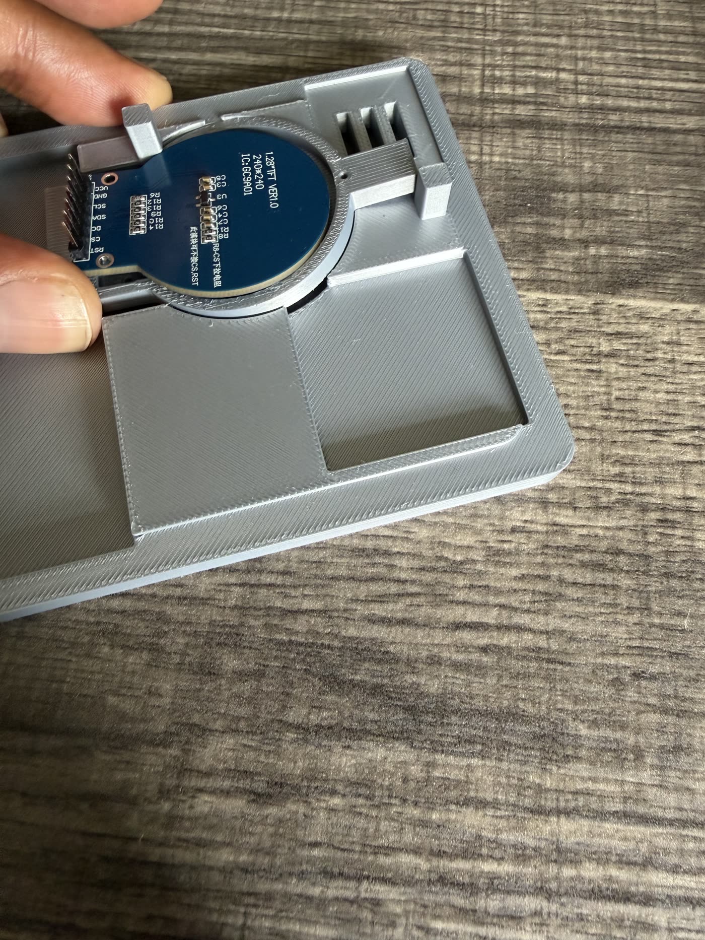
The display is a 1.28" 240 × 240 round TFT on a GC9A01 controller. Round displays are unforgiving in a way rectangular ones aren't: the bezel has to be concentric with the glass, not with the PCB it's mounted on, and those two circles are not the same circle.
We fit-tested it against printed lids repeatedly before committing. The pin header sticks out the side, so the lid needs clearance for the header and the wires leaving it — which is geometry that lives nowhere in the display's spec sheet.
Then it became a real board
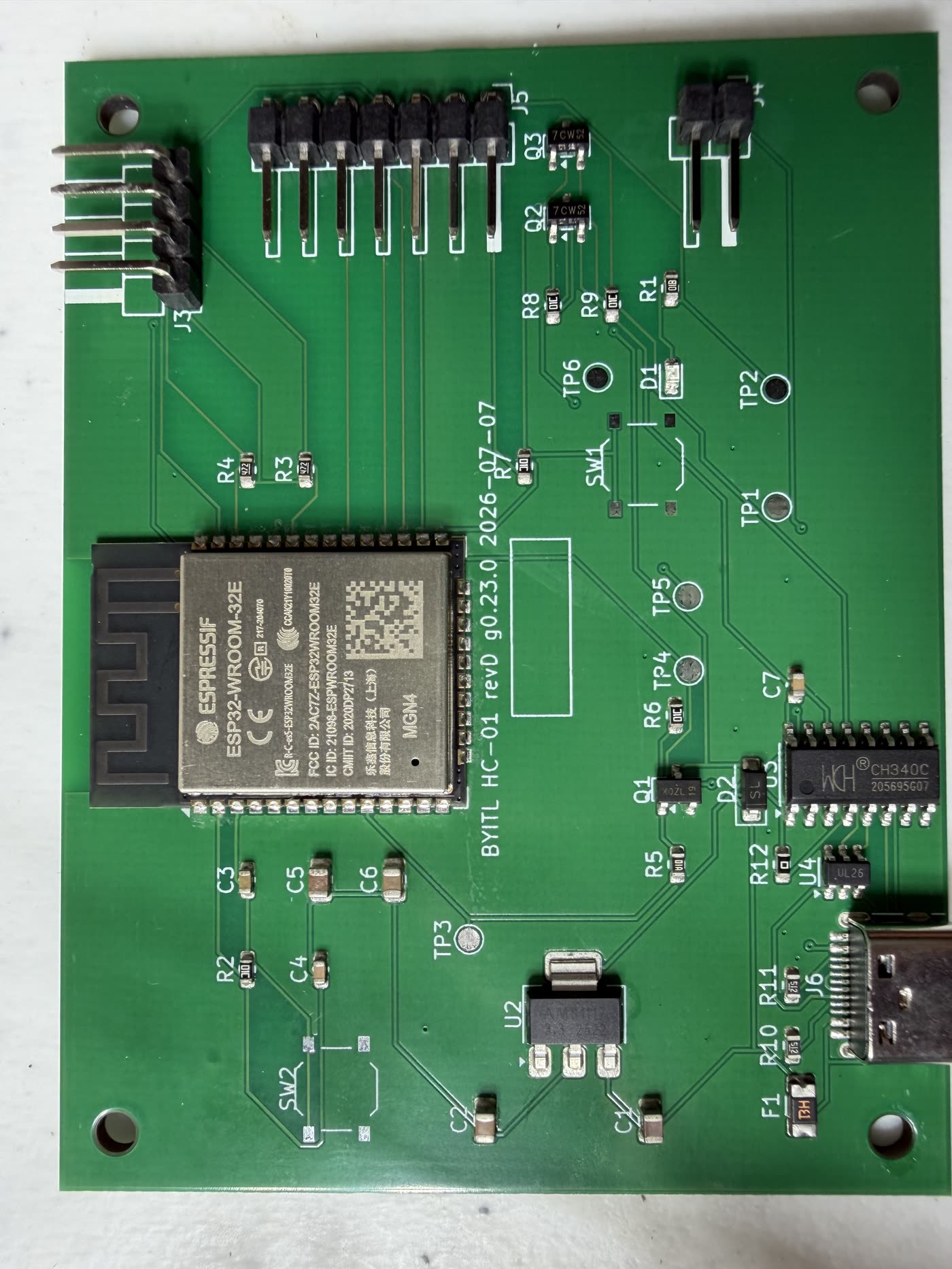
This is rev D — the fourth spin. Silkscreen reads BYITL HC-01 revD g0.23.0 2026-07-07. (The board is now on rev E; see part three.)
What changed from the rat's nest:
- One USB-C connector does everything. Power and programming, over a CH340C USB-serial bridge. The prototype needed a dev board's USB plus separate power; the product needs one hole in one wall.
- The headers encode the peripherals. J5 is 7-pin for the display, J3 is a right-angle 4-pin for the sensor, J4 is 2-pin for the fan. Every jumper wire in the prototype photo is now a trace.
- Test points, TP1 through TP6. Once the board lives inside a sealed enclosure, "just probe it" stops being free. You get the pads you designed in and nothing else.
Notice SW1 and SW2 are footprints with no switches on them. That's deliberate — the pads are there so a later revision can add buttons without a respin, and this build doesn't need them.
The fan is a sensor problem
The controller's whole job is to run a fan to keep humidity in range. But the SHT40 sits in the same box as the fan, which means an unqualified reading tells you about the air near the fan, not the air in the humidor.
So sampling has to be choreographed against the fan: purge, settle, then read. This is the kind of thing that looks like a firmware detail and is actually an enclosure decision — where the sensor sits relative to the airflow determines whether the number on the screen means anything.
36 seconds of it
What we'd tell you
If you're sitting on a working prototype, the gap to a product is mostly this:
- Get real geometry for every part. Not the chip — the module you're actually buying, with its headers and its wires.
- Fit-test early and physically. A print costs hours. A wrong assumption you don't find until rev C costs weeks.
- Design the board and the box together. Our connector placement exists because of where the walls are. Do those separately and you get a board that fits nowhere.
That's the job we do now — board, firmware and enclosure as one engagement, quoted after a 15-min call. If you've got the bench version working and need the rest, see how it works.
Related
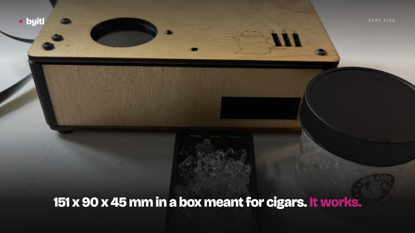
It works. It is also too big.
Part five. HC-01 is running in a real humidor: 522 logged samples, agreement with an independent hygrometer, and one closed control loop.
· 6 min read
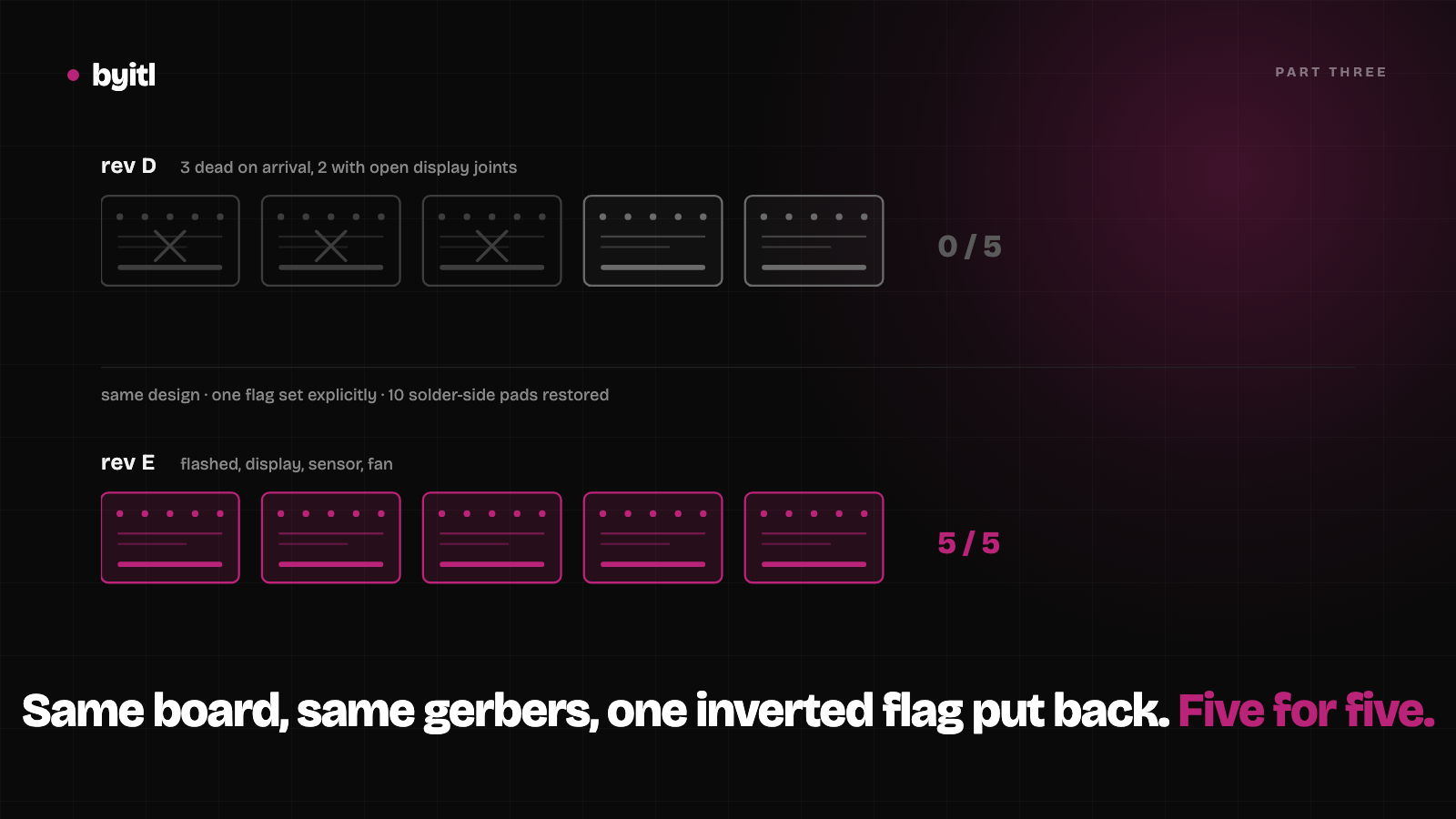
The annular-ring fix held: five of five boards work
Part three. Same design, one inverted flag put back, a different assembler. Five of five rev E boards flashed, drove the display and read the sensor.
· 8 min read
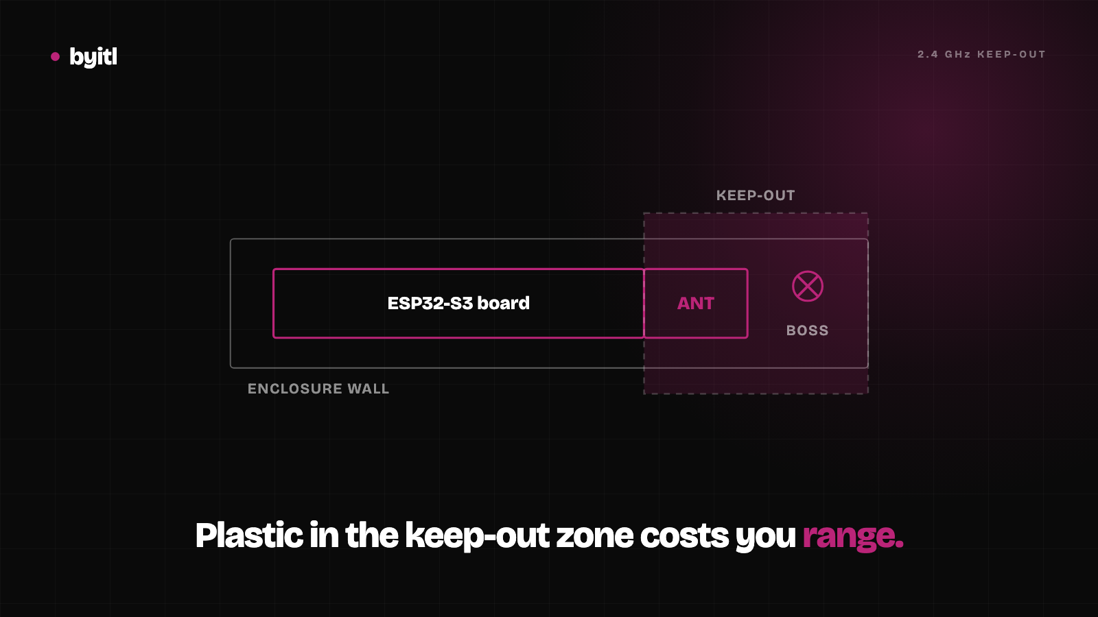
ESP32-S3 enclosure design: give the antenna its 15 mm
Espressif asks for at least 15 mm of clearance around an ESP32-S3's PCB antenna inside the housing. What that means for a 3D-printed case, with sources.
· 6 min read