
STEP vs STL: which file your enclosure design actually needs
Jerome Privott · · 11 min read
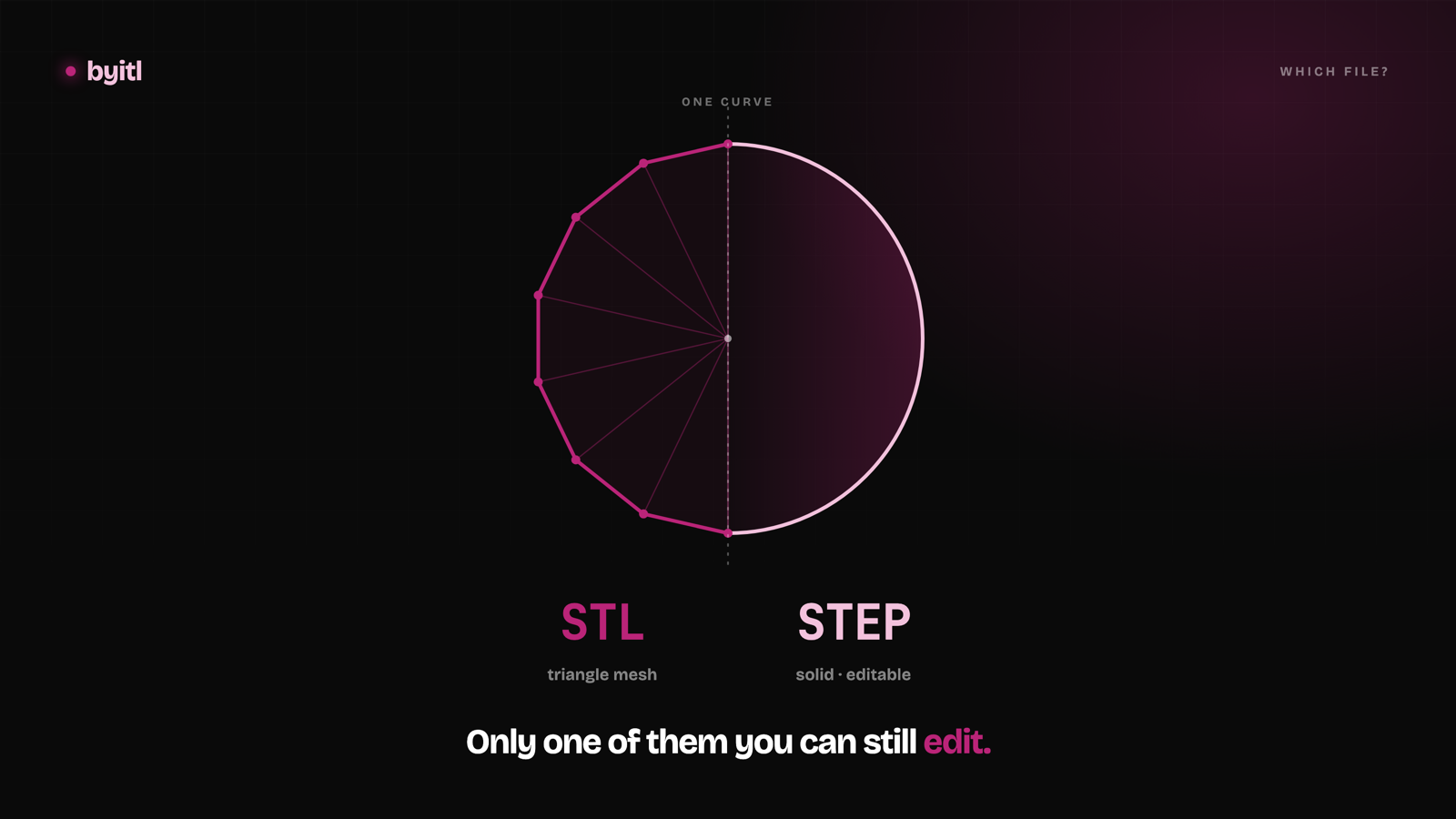
You exported a STEP file and your slicer won't open it. Or you have an STL and the shop just asked for "the real CAD." Or a designer handed you a folder of files and you don't know which one you're supposed to keep.
Short answer first, then the reasoning.
The short answer
- Slicers want mesh — STL or 3MF. PrusaSlicer, Cura, Bambu Studio, Orca. (Several now open STEP too, but they convert it to a mesh the moment it loads.)
- Anything that has to modify the part wants STEP. CAD, CNC quotes, injection-molding vendors, the next person who revs your board.
- STEP → STL is a normal export. It takes seconds and it's reliable. You pick a tolerance and you're done.
- STL → STEP is not really a conversion. It's reverse engineering, and you rarely get back what was lost.
- Keep the STEP. It's the original. The STL is a photograph of it.
That last point is the one that costs people money, so here's why.
What an STL actually is
An STL file is a list of triangles. That's the whole format.
Each facet gets three vertices and a unit normal — twelve numbers, and nothing else. No units: the original 3D Systems specification says outright that the file "does not contain any scale information; the coordinates are in arbitrary units." Whether they mean millimeters or inches is a convention between you and whoever opens it. No color. No materials. No assemblies. No layers.
And, critically: no features.
An STL does not know it has a hole in it. It has a ring of narrow triangles arranged in a circle-ish tube. It does not know it has a fillet — it has a strip of triangles that happen to curve. There is no cylinder in the file, no radius value, no sketch, no history of operations, no parameters.
This is what people mean when they say STL "loses design intent." It isn't sloppy — it's structural. A tessellation describes a surface. It cannot describe why the surface is that shape.
The practical consequence: you cannot cleanly change an STL. If your USB-C cutout is 0.3 mm too tight, you can't open the STL and type a new number. There is no number. You can push triangles around, or you can go back to the CAD — and if you don't have the CAD, you're remodeling the part.
What a STEP file actually is
STEP is ISO 10303 — a neutral CAD exchange format built on boundary representation, or B-rep.
Instead of approximating a surface with triangles, a B-rep model stores exact analytic geometry. A hole is a genuine cylindrical face with a genuine diameter. A fillet is a real toroidal or swept surface with a real radius. Curves are exact, not sampled.
This isn't marketing language — it's in the standard. ISO 10303-42, the geometry resource STEP builds on, defines its simple surfaces as "the planar, spherical, cylindrical, conical and toroidal surfaces, a surface_of_revolution and a surface_of_linear_extrusion," and states that these entities "support the requirements of simple boundary representation (B-rep) solid modeling."
That's why STEP is editable and why it's cross-vendor. Fusion 360, SolidWorks, Onshape, FreeCAD, Inventor, Creo — all of them read STEP and reconstruct actual geometry, not an approximation of it. The neutrality is the point: STEP is how you hand a part to someone who doesn't use your CAD package.
About the version numbers in your export dialog: most CAD tools still offer AP203 and AP214. Both were formally withdrawn by ISO on 2014-12-01 and replaced by AP242, which merged their capabilities — so that dropdown is very likely still offering you two retired standards. AP242 has been revised repeatedly since its 2014 first edition; the current fourth edition was published in August 2025. Pick AP242 when the receiving end supports it, AP214 as the fallback for older systems. For a prototype enclosure all three carry the solid geometry fine — the differences show up in manufacturing metadata (PMI, GD&T) that a fit-and-function print doesn't use.
STEP vs STL, side by side
| STEP | STL | |
|---|---|---|
| What's in the file | Exact surfaces (B-rep) | Triangle mesh |
| A hole is… | A cylindrical face with a diameter | A ring of flat triangles |
| Units | Stored in the file | Not stored — ambiguous |
| Editable in CAD | Yes, meaningfully | Not meaningfully |
| Feature history / parameters | No history, but real features | Neither |
| Colors, materials, assemblies | Yes (assemblies, some appearance) | No |
| Typical file size | Smaller for curved parts | Grows fast with curve fidelity |
| Slicers accept it | Some import it — tessellated on load | Yes — this is its native job |
| Machine shops & molders want | This one | Not this one |
| Standard | ISO 10303 (AP242 current) | De facto; the original 3D Systems spec, no governing body |
Direction matters more than anything else
This is the part most "STEP to STL converter" pages skip, and it's the part that determines whether you have a problem or a five-second task.
STEP → STL: routine
This is just tessellation. The CAD kernel already knows the exact geometry; it walks the surfaces and generates triangles that stay within a tolerance you specify. Every CAD package does it. It's the standard last step before printing.
It's lossy — you're throwing away the exact geometry — but it's lossy in a controlled, predictable way, and you still have the STEP. Nothing is actually lost as long as you keep the original.
Worth knowing: the slicers that accept STEP directly are doing exactly this for you, silently. PrusaSlicer has imported STEP since 2.5, and Prusa is blunt about what happens next — "we are tessellating the model on import (converting it to a triangle mesh), so the model is then sliced just like any other mesh and not analytically." Opening a STEP in a slicer is not slicing CAD. It's an STL export you didn't get to configure.
STL → STEP: the hard direction
Here you're going the wrong way up the hill. You have triangles and you're trying to recover the surfaces they were sampled from. That's reverse engineering, and it's genuinely hard.
The usual result is what people call a dumb solid: a file that is technically valid STEP, that opens in your CAD package, and that consists of several thousand tiny planar faces — one per triangle. It's a solid. It is not editable in any way you'd want.
Your hole is still a polygon. It's now a polygon made of proper B-rep planar faces instead of mesh triangles, which is a change in file format and not a change in the geometry. You still can't select it and change the diameter, because there is no diameter — there are thirty-two flat faces in a ring. Applying a ±0.05 mm tolerance to that bore doesn't mean anything, because the bore isn't round.
Xometry puts the underlying problem plainly: "STL file data does not contain information on curves. Any curve, radius, circle, etc., will comprise a series of lines and planes." The resulting STEP "does not inherently support parametric editing unless the geometry is rebuilt manually or using advanced recognition tools."
Better tools do try to fit real surfaces — recognize that a ring of facets "wants" to be a cylinder, and replace it with one. Some manage this on simple prismatic parts. Results degrade fast with organic shapes, dense scan meshes, and anything with blends. Treat automatic mesh-to-B-rep as a starting point for remodeling, not a recovery of the original.
The rule this leads to: get the STEP from your designer up front, while it costs nothing. Recovering it later costs a remodel.
The knob that matters on export: tessellation tolerance
When you export STEP → STL, your CAD asks for a tolerance. It might be called chord height, deviation, linear tolerance, or just "resolution." It's the same idea: how far is the flat triangle allowed to sit from the true curved surface?
Set it too coarse and curved surfaces come out visibly faceted — a round boss looks like a nut, and a lens window prints with flats you can feel. Set it too fine and the triangle count explodes; the file gets large and slow to slice with no visible benefit, because you've gone well below what the printer can resolve anyway.
There's a subtler issue that matters for enclosures specifically, and it depends on your exporter. Every tool defines this setting as a maximum distance between the true surface and the mesh — SolidWorks, Fusion 360, and the Open CASCADE kernel behind FreeCAD all describe it that way, and none of them document which side of the surface the triangles land on. Many exporters put the triangle vertices on the true circle, which leaves every flat slightly inside it and makes a tessellated hole measure undersized across the flats. Others spread the deviation across the surface instead. So don't assume — check yours, because if you're press-fitting a Ø5 mm LED or dropping in a heat-set insert, a coarse tolerance can quietly eat a clearance you budgeted carefully. When a part fits in CAD but binds after printing, this is one of the first things to measure.
A reasonable habit: export at a tolerance meaningfully finer than your printer's resolution, look at the preview, and go finer only if you can see facets on a curve you care about.
Where 3MF fits
3MF is the modern answer to STL's limitations, and it fixes the obvious ones. Its core specification defines a unit attribute on the model itself — "valid values are micron, millimeter, centimeter, inch, foot, and meter" — so a model can't silently arrive at 25.4× the wrong size. It carries color and material assignments. It holds multiple objects in one file, each with its own transform. And it stores vertices once in a shared list that triangles reference by index, instead of repeating coordinates per facet the way STL does, which makes files smaller.
Slicer support is good — PrusaSlicer, Cura, Bambu Studio, and Orca all read 3MF, and several use it as their native project format. One gotcha: Bambu Studio's project 3MF carries Bambu-specific extensions that core 3MF doesn't define, and those files historically didn't open cleanly everywhere. Bambu ships a File → Export → Generic 3MF option for exactly this reason — the generic export is, in their own moderator's words, "the standard 3MF without any of those BL-specific extras." PrusaSlicer merged support for the Production Extension in March 2024. If a 3MF won't open in another slicer, that's usually why.
What 3MF is not: a replacement for STEP. It's still a mesh — a better mesh than STL in every respect, but it won't give you back an editable hole diameter. STL vs 3MF is "which mesh." STL vs STEP is "mesh or CAD." Different questions.
Which do I ask for?
- Printing it yourself, today → STL, or 3MF if your slicer prefers it.
- Sending it to a print service → STL. Confirm units, since STL doesn't carry them.
- CNC machining quote → STEP. A shop that receives an STL will ask for STEP, or quote defensively.
- Injection molding / tooling quote → STEP, and expect DFM questions about draft, wall thickness, and undercuts.
- You might rev the board → STEP, without question. Connector moves 2 mm, you change one number.
- Handing it to another engineer → STEP. Send the STL too, so they can print without a CAD session.
- Archiving the project → STEP is the master. Regenerate STLs from it whenever you need them.
- Someone only gave you an STL and you need to edit it → budget for remodeling, not converting. Ask whoever made it for the source file first; that's a two-minute favor versus a day of your time.
Why this shows up constantly in enclosure work
A hardware prototype almost always needs both. You print the enclosure this week — that's mesh. You rev the board next month and the USB-C port moves 3 mm — that's CAD. If the only file you own is the STL, the second job means starting over.
This is why byitl ships both on every engagement: print-ready STL, oriented and watertight, plus the editable STEP for every printed part. You can see what that looks like in the samples, where most design packs are free to download. A fair amount of cheap enclosure work hands back mesh only, which quietly makes you dependent on whoever holds the source — we'd rather give you the file that lets you leave.
One limit, stated plainly. The STEP is a fit-and-function prototype file, not DFM-certified for production tooling. Going to molding means draft angles, uniform walls and undercut elimination, and that's a separate engagement.
Our work now covers the whole device: the circuit board, the firmware and the enclosure, with one working unit at the end, from $7,500. If that's what you're building, see how it works. If you only needed to know which file to ask for, the useful half of this post was free anyway: keep the STEP.
Related
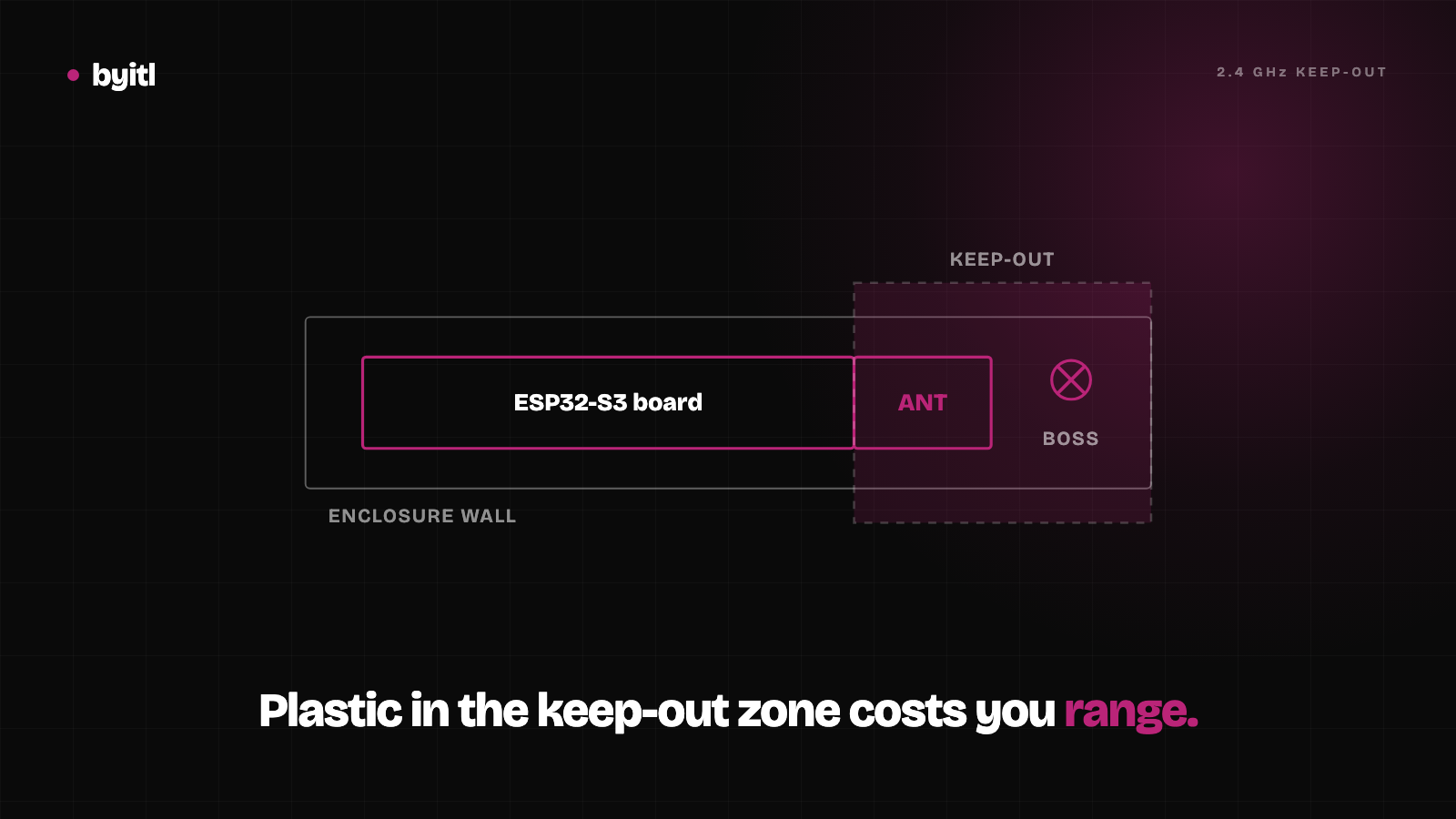
ESP32-S3 enclosure design: give the antenna its 15 mm
Espressif asks for at least 15 mm of clearance around an ESP32-S3's PCB antenna inside the housing. What that means for a 3D-printed case, with sources.
· 6 min read
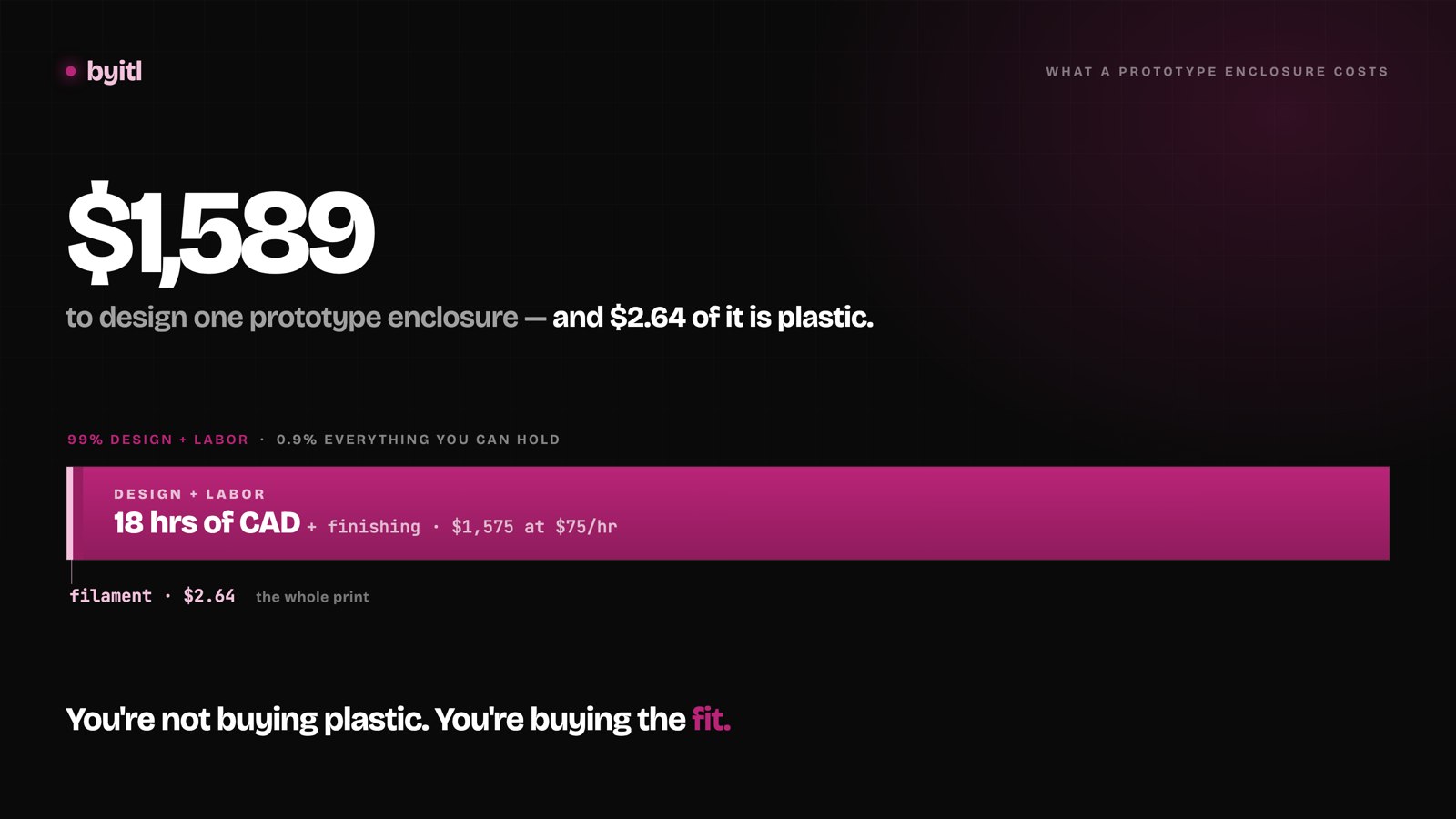
What a 3D-printed prototype enclosure actually costs in 2026
Filament is under half a percent of the bill. Here's the itemized total for a palm-sized ESP32 enclosure, design time included.
· 10 min read
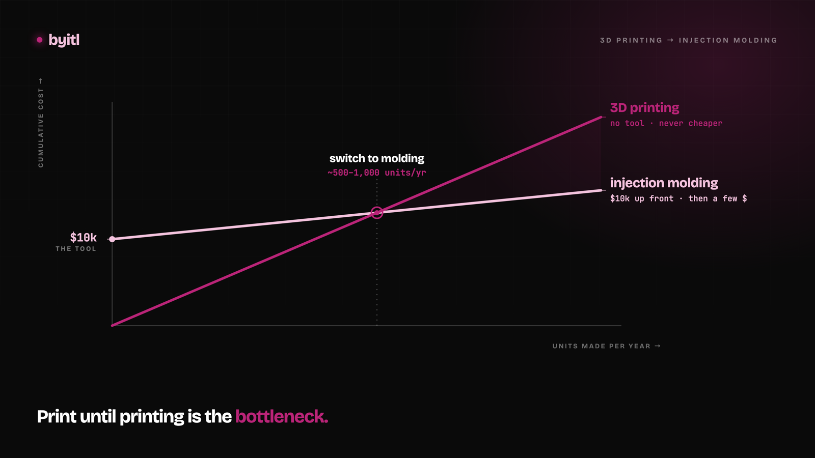
From 3D-printed enclosure to injection molding: when to switch
A single-cavity prototype steel tool for a palm-sized enclosure runs about $10k — we've had our own parts quoted. Here's the break-even math on when it pays.
· 10 min read