
The annular-ring fix held: five of five boards work
Jerome Privott · · 8 min read
The fix, on hardware
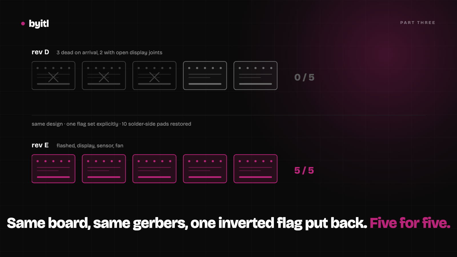
Part one was five assembled boards arriving defective: three dead on the USB-C power path, and two that powered up but had an open display header. Part two found the cause of the second fault, and that one was ours. A parser inverted remove_unused_layers and stripped the bottom annular ring off every through-hole pad on the board.
That bug does not explain the other three, and I should not have written as though it did. The USB-C power path is entirely surface-mount: J6 carries sixteen SMD pads and only four through-hole legs, and those four are the shield tabs, not VBUS. F1 is an SMD 1206 polyfuse. The regulator is an SMD SOT-223. The annular-ring bug removed bottom-layer copper from through-hole pads only, so it could not have touched any of it. Three boards with 0 V at TP1 failed on a path our gerbers never affected.
So rev D had two separate faults, and only one of them was ours. That is also why the failures were inconsistent board to board, which is exactly what the claim rested on: a design fault fails identically every time, and these did not.
Rev E is the same design with that flag set explicitly. Part two measured what came back on the bottom copper layer: ten pad flashes restored, three of them on the display header whose pins had measured open.
Five assembled rev E boards came back from PCBWay, order T-2Y3W1181519A, BOM dated 7 August. I flashed and tested all five.
All five work.
Five for five
| Board | Serial | Display | SHT40 | Fan |
|---|---|---|---|---|
| 1 | 3076F5750FDC |
yes | 48.4 %RH / 23.2 °C | yes |
| 2 | 3076F5750FBC |
yes | 45.3 %RH / 24.8 °C | yes |
| 3 | 3076F5750F90 |
yes | 48.5 %RH / 23.3 °C | yes |
| 4 | 3076F5750FA4 |
yes | reading confirmed on screen | yes |
| 5 | 3076F5750FB8 |
yes | 48.3 %RH / 22.6 °C | yes |
Board 4's sensor reading was read off the display rather than the serial log. I unplugged it before capturing one, and I am not going to write down a number I did not record.
Every board dropped into the bootloader on its own and took the image with no button presses, which is the DevKitC auto-reset circuit doing its job through the onboard CH340C. The qualification image is the product firmware with three compile-time switches turned on: a solid-colour fill before the UI starts, a shortened purge cycle so a sensor reading arrives in seconds instead of sixteen minutes, and a square wave on the fan line.
Board 5, verbatim:
I (705) byitl_identity: BYITL HC-01 revE fw0.1.0 g0.31.0
I (715) byitl_identity: serial 3076F5750FB8
W (1345) display_task: BRINGUP: pass 1/3 -- WHITE
W (13025) display_task: BRINGUP: solid-fill done -- handing off to LVGL
I (26225) sensor_task: purge sample: rh=48.3% t=22.6C
W (31185) sensor_task: FANBLINK: fan ON  (controller wanted ON)
Boards 1, 3 and 5 were measured within minutes of each other in the same room and agree to 0.2 %RH. That is the check that the sensor is reporting the room and not a plausible constant.
Two of the five failed the sensor on the first attempt. Both were the J3 wiring, not the board. The header runs 3V3, GND, SDA, SCL, and the sensor breakout silks VIN, GND, SCL, SDA, so a straight ribbon crosses the bus. Same board, same firmware, rewired by function, and it read rh=48.4% t=23.2C.
What this does not prove
Two things changed between the batches: the annular-ring fix and the assembler. I cannot separate them with this data. The clean test would have been the corrected gerbers back to the same fab, and I did not run it.
That cuts both ways, and it is worth being precise about which half each change could have fixed. The annular-ring fix can only account for the display-header fault, because that is the only one that lived on through-hole pads. It has no bearing on the three boards that never powered up. Those were an all-SMD path, so whatever went wrong there was assembly, not artwork, and the thing that changed for them was the assembler.
So the narrow version is the one I will stand behind. The pads that were missing are present. The header whose pins measured open now drives a display on five boards out of five. The power path that killed three boards came up on all five. Nothing failed.
That is weaker than it looks in a headline and stronger than what I had before, which was a hypothesis and a parser diff.
PCBWay
Five for five, assembled, first attempt, nothing reworked and nothing to send back. Both of the failure modes from the last batch are simply gone: every board enumerated over USB-C, and the display header that had pins measuring open is driving a panel on all five.
I have no instrumented view of how they run a line, so I cannot tell you anything about their process that I did not measure myself. What I can tell you is the outcome, which is the thing I was actually buying. They built what the gerbers described, and the boards worked when I plugged them in.
That sounds like a low bar. It is the entire job, and after the last round it was a genuine relief to have a batch that just worked. They get our next run.
The firmware had its own bugs
The boards being good exposed two problems that bad boards had been hiding.
The user interface rendered mirrored. Readable in a mirror, on every unit. The bench project is the only configuration ever validated against this GC9A01 module, and the product firmware had inherited three of its four display settings. It took the colour order, the inversion and the byte swap, and left mirror_x behind.
/* bench, validated */        /* product, shipped */
.mirror_x = true,            .mirror_x = false,
The second was identity. board_pins.h and the CMake defines both still said rev D, so every unit introduced itself as BYITL HC-01 revD fw0.1.0 g0.23.0 in its banner, its web interface and its serial registration. The GPIO map is byte-identical between the two revisions, so nothing misbehaved. It was just wrong, on hardware that was about to get its serial written into a product registry. Regenerated from the rev E board contract, it now reads revE fw0.1.0 g0.31.0.
Worth knowing if you are wiring one: the J5 display header changed pin order in rev E. Rev D ran RES, DC, CS on pins 5 to 7 and needed a crossed cable. Rev E runs DC, CS, RST, which matches the module silk, so a straight cable is now correct and the old harness is wrong.
Board 2 went the rest of the way
One board was taken through the whole path. Provisioned onto Wi-Fi, where it now reconnects unattended on boot. Its web interface serves in 70 ms and rejects an out-of-range setpoint with a 400 and a reason rather than a silent clamp. Firmware updated over the air, 1,322,160 bytes in 14.1 seconds, and the device came back on the other flash partition:
boot: Loaded app from partition at offset 0x1a0000
That is the OTA slot rather than the factory one, which is the part that matters. It rejoined the network by itself and the web interface came back on the same address.
What is not done
Provisioning from a phone does not work, and that is a shipping problem rather than a bench quirk.
The firmware authenticates with protocomm security2, which takes a username and a password. The stock Espressif apps mostly offer a single proof-of-possession box, which is a security1 client and cannot express a username at all. I changed our username to Espressif's default to give the stock app a chance. It still fails:
E security2: psa_aead_decrypt failed with status=-149
E protocomm: Decryption of response failed for endpoint prov-scan
That is an invalid signature. The session key the app derives does not match the device's. Board 2 was provisioned with the command-line tool instead, which a customer has no reason to own. We are building our own app.
There is a worse finding underneath it. A failed provisioning attempt panics the unit:
assert failed: tlsf_free tlsf.c:630 (!block_is_free(block) && "block already marked as free")
A double free on the decryption-failure path, and the device reboots. It is upstream rather than ours, as far as I can tell: no teardown ran before the assert, and board 2 came through the same teardown without incident. Either way it means someone in Wi-Fi range can reboot an unprovisioned unit by fumbling the PIN, and that has to be handled before any of these ship.
What I took from it
The thing I got wrong this week was not the fix. It was spending two hours on a display fault that was a cable.
A panel that stayed black while the backlight was on, with the firmware reporting every write successful. The display header carries no return line, so the bus is write-only: the driver reports success into thin air, and LCD panel create success logs identically with nothing attached. I moved the display to a second board to isolate it and got byte-identical readings, which I read as proof the board was fine and the module was suspect. The cable had moved with the display. Swapping to fresh jumpers fixed it in seconds.
Three conductors in that harness were good, VCC, ground and reset, and four were open. That is why the module powered up, lit its backlight and flashed when reset toggled, while nothing ever reached the panel.
When the symptom is a dead peripheral on a bus you cannot read back, swap the cable before you swap the board.
We design the board and the enclosure as one job, and we test the boards when they come back. See how that works.
Related
Custom PCB fabrication: three of five boards arrived dead
Three of five assembled boards arrived dead. The defect wasn't ours, and proving that took test points we had added a month earlier.
· 6 min read
We told the fab the missing annular rings were intentional. They weren't.
Part two. The fab asked about one thing before building. We said it was deliberate. It was a parser bug, and it is why only the through-hole joints failed.
· 7 min read
From jumper wires to a custom PCB: building the HC-01 humidor controller
An ESP32 rat's nest became a four-revision custom board. The most expensive mistake was a sensor we never actually measured.
· 4 min read