
The probe said OPEN. The display was working.
Jerome Privott · · 6 min read
A probe that could not pass
Part three ended with two hours lost to a display harness, and the lesson I took from it was to swap the cable before you swap the board. That is the right lesson. It is not the interesting one.
The interesting one is that I wrote an instrument to find that fault, the instrument answered me, and the answer carried no information at all.
Here is the setup. The round display hangs off J5, and J5 has no MISO:
#define PIN_VSPI_RES  4
#define PIN_VSPI_CS  16
#define PIN_VSPI_DC  17
#define PIN_VSPI_SCK 18
#define PIN_VSPI_MOSI 23
Five pins, no return path. esp_lcd_panel_draw_bitmap() returns ESP_OK whether or not anything is on the other end of the wire, and gc9a01: LCD panel create success logs identically with nothing connected. The firmware is blind to this failure by construction, so I built something that wasn't.
The module silkscreen says R8-CS下拉电阻 — R8 is a CS pull-down, sitting at the far end of the line. That makes a meter-free continuity test possible. Float the board's CS pin as an input with the ESP32's internal pull-up, roughly 45 kΩ, and let it fight R8 at roughly 10 kΩ:
- reads LOW → R8 is winning → trace, J5 joint and cable are all intact
- reads HIGH → nothing out there → the chain is open
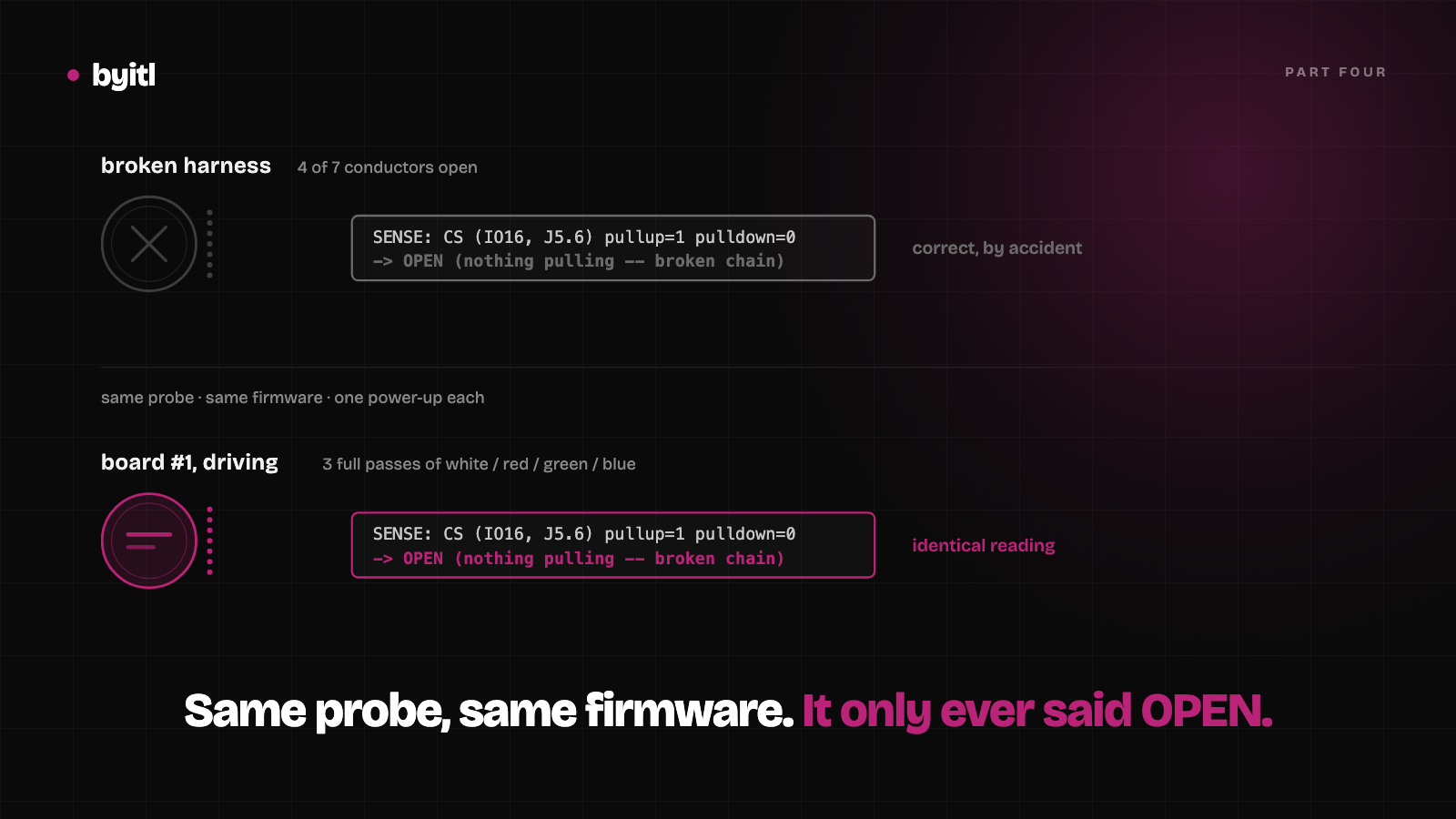
I ran it. It said open. The harness was in fact open on four conductors, CS among them, and fresh jumpers fixed the display in seconds. The probe had called it.
The same reading, on a board that works
Two days later I was qualifying the rest of the batch and left the probe compiled in. Board #1, same firmware, same probe, one power-up. This is boot-board1-ok.log, trimmed to the two things that matter:
W (1297) display_task: SENSE: CS   (IO16, J5.6) pullup=1 pulldown=0  -> OPEN (nothing pulling -- broken chain)
...
W (1537) display_task: BRINGUP: pass 1/3 -- WHITE
W (2517) display_task: BRINGUP: pass 1/3 -- RED
W (3497) display_task: BRINGUP: pass 1/3 -- GREEN
W (4477) display_task: BRINGUP: pass 1/3 -- BLUE
Those lines are 1.2 seconds apart on the same boot. The probe says the CS chain is broken. Then the panel takes three full passes of white, red, green and blue, which it cannot do unless CS is being driven end to end.
So R8 is not there. The silk says it is. The behaviour says it is not — unpopulated, or far too weak against a 45 kΩ internal pull-up to move the pin. Either way the probe reports OPEN on a broken cable and on a working one alike.
It has no pass state. I shipped a test that could only ever return one answer.
It agreed with me once, by accident
The failure here is not the electronics. The reasoning about R8 was sound, and if R8 existed the probe would work exactly as described. The failure is that I ran it once, on a broken board, got the answer I expected, and called that validation.
One observation consistent with a hypothesis is not a test of the hypothesis. I never ran the probe on a known-good board, which is the single cheapest thing I could have done: thirty seconds, a working display, and it would have printed OPEN and gone straight in the bin.
I have corrected it in the firmware rather than deleting it, because half of it does work:
{PIN_VSPI_CS,   "CS  ", 6, 0},   /* NOT diagnostic -- R8 unpopulated */
{PIN_VSPI_RES,  "RST ", 7, 1},   /* diagnostic -- real module-side pull-up */
RST has a genuine pull-up on the module, so reading HIGH with the internal pull-down enabled proves that conductor is continuous. That half was correct on every board tested. The commit that fixes this says it plainly, because the next person to read the log deserves better than I gave myself:
It reports OPEN on a broken cable and on a working one alike, so R8 is unpopulated on these modules (or far too weak against the ~45k internal pull-up) and the reading carries no information.
The second instrument changed what it measured
Bring-up firmware is code, and it is the least-tested code in the project. It runs once, on a broken board, at the point where you are most tired and most inclined to believe it. Mine lives behind compile-time switches that all default to zero:
| Toggle | What it does |
|---|---|
HC01_BRINGUP_FILL |
Solid white/red/green/blue fill before LVGL starts |
HC01_BRINGUP_SENSE |
The J5 continuity probe above |
HC01_BRINGUP_HOLDHIGH |
Holds all five display lines at 3.3 V for 180 s for metering |
HC01_BRINGUP_SWEEP |
Four labelled trials of reset-method × SPI clock |
HC01_BRINGUP_FASTPURGE |
Shortens the purge cycle so a reading arrives in seconds, not 16 minutes |
HC01_BRINGUP_FANBLINK |
Square-waves the fan, bypassing the controller |
The qualification image has three of them on. FANBLINK exists for a good reason. On an open bench the room sits far below a 70 % setpoint, so the controller correctly asks for the fan continuously and never exercises the off path — which is also exactly what a shorted MOSFET looks like. The flag drives the pin both ways on purpose to tell those two apart:
fan_effective = ((now_s % 6) < 3);
Three seconds on, three seconds off, controller ignored. You can watch it overrule the control loop in the log:
W (7197) sensor_task: FANBLINK: fan ON (controller wanted OFF)
That image went onto the demo board on 3 October. I did not take it off. Two days later the bench report was that the fan cycled every few seconds no matter what the humidity read, which is not a control bug, a sensor bug or a MOSFET bug. It is now_s % 6.
I want to be exact about the evidence, because I did not capture a serial log from that board before reflashing it. What I have is the image and the symptom. The image is still on disk, and it answers the question in one line:
$ strings -a qual-image.bin | grep -c FANBLINK
1
$ strings -a build/humidor.bin | grep -c FANBLINK
0
The second one is the production build. That grep is now the release check, because "I remember turning it off" has a demonstrated failure rate.
There is a second-order cost worth naming. A fan running half the time on an open bench pulls room air across the SHT40, so every humidity figure taken while that flag was live is suspect. The instrument did not just report the wrong thing. It changed the thing it was reporting on.
What I actually changed
Two rules, both cheap, both of which I had skipped.
A diagnostic gets a known-good reading before I trust a bad one. If it cannot distinguish a working board from a broken one, it is not a diagnostic, however sound the physics behind it looks on paper.
Anything that alters product behaviour has to be provably absent from the shipped binary, by a command rather than by memory. A compile-time switch is good design and it is not a guarantee. The guarantee is grep -c returning zero.
Neither of these would have saved me the two hours on the cable. Both would have saved me from publishing a continuity test that cannot fail, and from handing over a board that cycles its fan on a timer.
We design the board and the enclosure as one job, and we write the firmware that proves the board works. See how that works.
Related
The annular-ring fix held: five of five boards work
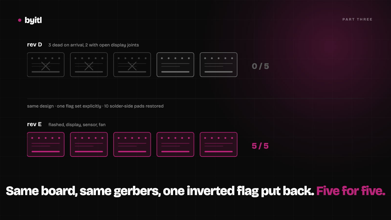
Part three. Same design, one inverted flag put back, a different assembler. Five of five rev E boards flashed, drove the display and read the sensor.
· 8 min read
Custom PCB fabrication: three of five boards arrived dead
Three of five assembled boards arrived dead. The defect wasn't ours, and proving that took test points we had added a month earlier.
· 6 min read
From jumper wires to a custom PCB: building the HC-01 humidor controller
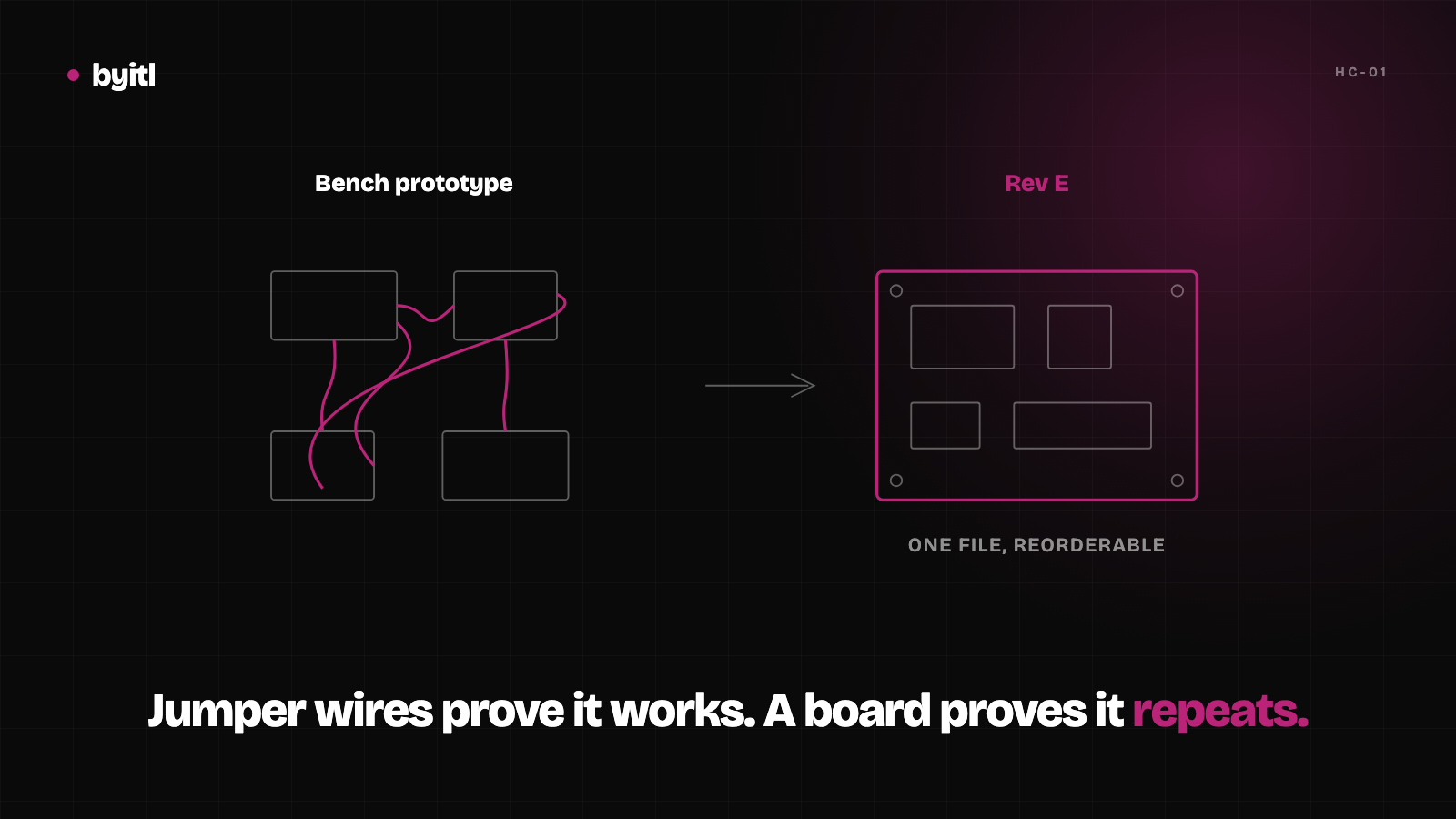
An ESP32 rat's nest became a four-revision custom board. The most expensive mistake was a sensor we never actually measured.
· 4 min read